Data Update Between AutoCAD and Maximo
Background
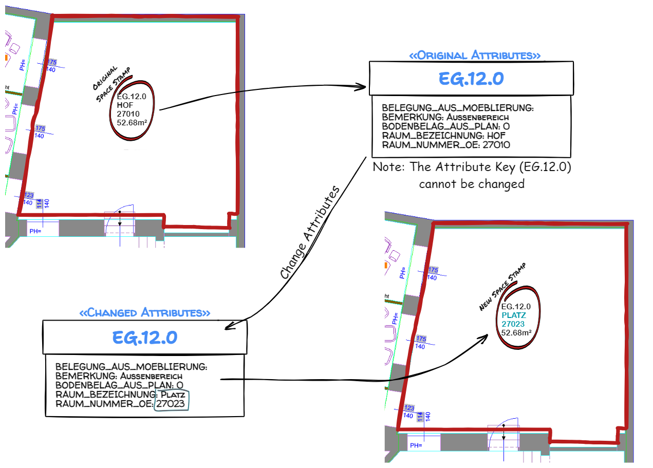
Bank of Austria wants to be able to change the values of a subset of attributes defined for blocks in their drawings. They do not want to change all of the attributes and they only want to change the attributes on a given type of block, RNB-VBF, also known as Space Stamps.
The data for the attribute modification will come from Maximo.
Process
The ultimate controlling data source is the collection of AutoCAD DWG drawings. The following is the Data Cycle:
-
The data is extracted from the AutoCAD drawings and put into Maximo.
-
The data is then changed in Maximo
-
A process is done to update the data back in the DWGs.
It is that final step, updating the DWGs, that is described here.
Data Extraction into Maximo
The data extraction step is handled by software written by Omninecs. However, it utilizes the SVG file produced by AutoXChange from Tailor Made Software. The minimal command line to produce a SVG with all Blocks (except for Anonymous Blocks which used for internal processes in AutoCAD (*D### blocks used for Dimensions, *X### for Hatches, *A### for Groups, *U### for Anonymous Blocks and *E### for anonymous non-uniformly scaled blocks) is:
-i=<input_file>.dwg -f=svg -rl=<roomLayer>-ak=* -ia -tl=<room_id_layer>
The parameters are:
| Parameter | Purpose |
|---|---|
| -i=<intput_file>.dwg | The input file name, it is usually fully qualified, otherwise it is relative to the current directory |
| -f=svg | The output format to create. -svg is valid too |
| -rl=<roomLayer> | The Layer of the Room Polygon [the polygon that surrounds each defined room in the drawing]. This is RAU-PL for BoA drawings. |
| -ak=* | The Attribute Key. This is used to determine which Blocks to process. * means to process all blocks with Attributes. If a key is listed (e.g. -ak=RAUM_NUMMER) then only those blocks that have a corresponding Attribute with that Attribute Key (as the Tag not the Value) will be processed. |
| -ia | Process Invisible Attributes - will output all Attributes on a block, not just those that are visible |
The following optional parameters are often used:
| Parameter | Purpose |
|---|---|
| -o=<output_file>.svg | The output file name, it is usually fully qualified, otherwise it is relative to the current directory |
| -blockname=ABC | Used in place of -AK to define the block(s) to process. Separate blocknames with a semicolon (;) |
| -tl=<room_id_layer> | The Text Layer. This is the layer of an Room ID text used in place of the XData RoomId used in Planon. The Room ID is a Text Object (containing the RAUM_NUMMER in the case of Bank of Austria) placed on the layer defined by -tl, physically inside the room polygon. Either the XDATA or the -tl layer MUST be defined for each polygon. If both are defined the RoomID from the -tl layer is used. |
Data Output from Maximo
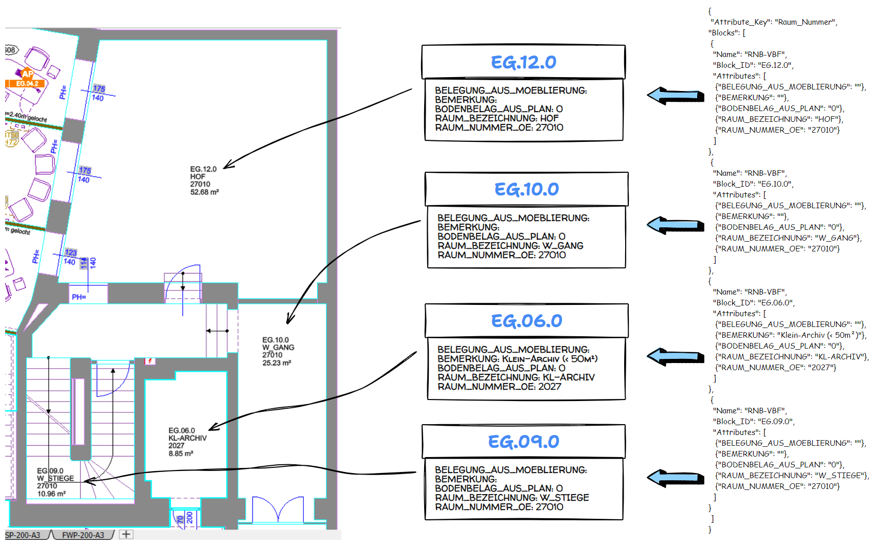
Data output from Maximo will be handled via JSON files. The JSON will define objects for each Space Stamp that has changed and will contain the Data Key (Room ID or Raum Nummer in this case) and the Name/Value pairs for each of the Attributes. The data objects can contain all possible fields or just those fields that changed. Either works just fine.
Please see section Processing Order on how the definition fields are processed.
The minimal JSON structure for identifying and modifying a simple block object is:
{
 "Attribute_Key": "RAUM_NUMMER",
 "Blocks": [
  {
  "Block_Name": "RNB-VBF",
  "Block_ID": "value",
  "Attributes": [
   {"BELEGUNG_AUS_MOEBLIERUNG": "value"},
   {"BEMERKUNG": "value"},
   {"BODENBELAG_AUS_PLAN": "value"},
   {"RAUM_BEZEICHNUNG": "value"},
   {"RAUM_NUMMER_OE": "value"}
  ]
}
}
This assumes that:
- The block already exists
- There is only one block of that type in a given area (since the Block_ID is based on the Room Number)
For the diagram shown under Process, the JSON data with the maximum number of fields would be: (Please see section Processing Order on how the definition fields are processed.)
{
 "Attribute_Key": "RAUM_NUMMER",
 "Blocks": [
 {
  "Block_Name": "RNB-VBF",
  "Block_ID": "EG.12.0",
  "Handle": "B0C23B4",
  "Use_XRecord": true,
  "Outline_Handle": "B0C23CD",
  "Location": {"x": "-4649.31", "y": "101.971"},
  "Attributes": [
   {"BELEGUNG_AUS_MOEBLIERUNG": ""},
   {"BEMERKUNG": ""},
   {"BODENBELAG_AUS_PLAN": "0"},
   {"RAUM_BEZEICHNUNG": "HOF"},
   {"RAUM_NUMMER_OE": "27010"}
    ]
  }
  ]
}
Each Stamp is defined by an object. The total file is built as an array of objects. Any object that is not to be changed does not need to be listed, however it does not hurt anything if it is listed except a few compute cycles to change the Attributes to the same values they were already at.
Update Space Stamps
The BODENBELAG_AUS_PLAN and RAUM_NUMMER_OE may be integers instead of strings. If so the quotes can be omitted.
A Note on the Attribute Key
It must be possible to uniquely identify which Space Stamp is being described. There can be only one Space Stamp per area on these drawings. The areas/rooms are uniquely identified with their ID or Raum Nummer (Room Number in English). So the Attribute Key uniquely identifies which Space Stamp should be updated. The Attribute Key should not be changed.
DWG Update
The DWG Update program will take each of the JSON objects and modify the AutoCAD DWG drawing to change the Attributes attached to the given Space Stamp.
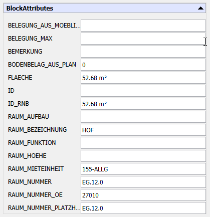
The image below shows all of the Attributes defined for the Space Stamp Block (type RNB-VBF). Only a small subset can be changed via this procedure.
Data Update Functions
A generic Block Type can have three functions done to it: Create, Modify, and Delete. Different data is mandatory for each of these functions.
Create
Create is the most complicated of the functions because the location of the Stamp must be defined within the Outline Polygon (Room Outline in this case).
The following data is required for Create:
1) ID - this defines what the new block will be known as. Handle cannot be used since it does not exist before the block is created 2) One or more of the three Location forms 3) The Attributes - List all attributes in the block to be created, all given Attributes can be listed, but the Attribute with the ID will always be created.
Modify
The following data is required for Modify:
1) Block ID or Block Handle - this identifies which block is being modified. Only one is needed
2) The Attributes - Some or all of the key five attributes may be listed. Any non-changed Attributes do not have to be listed
Optionally the location can be listed, but it is not required.
Delete
The following data is required for Delete:
1) Block ID or Block Handle - this identifies which block is being deleted. Only the first one listed is used unless there is more than one of a given Block Type in a Room, in which case the Block Handle must be given
2) The “Delete” keyword with the value of true
{
  "Block_ID": "EG.12.0",
  "Handle": "B0C23B4",
  "Delete": true
}
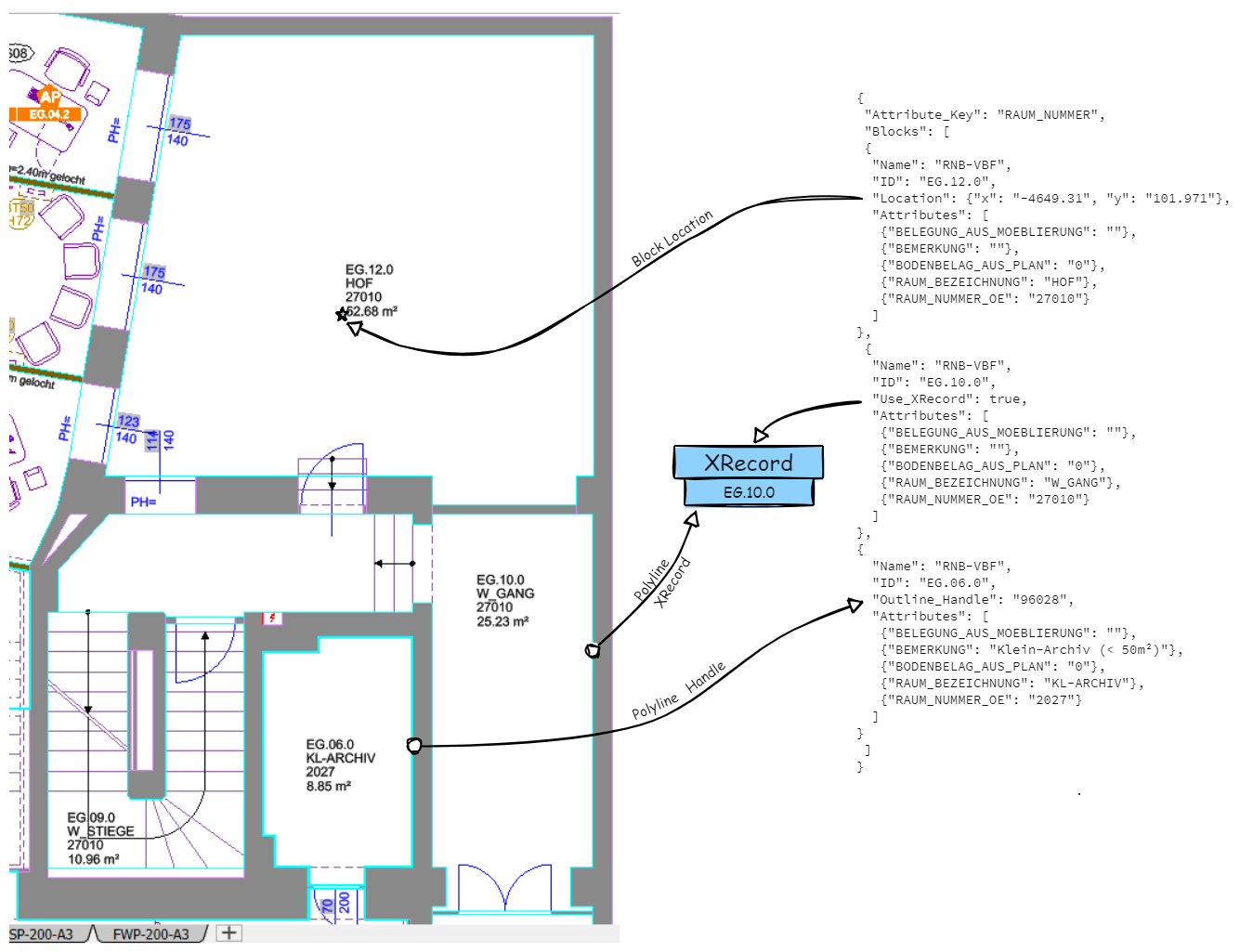
Location
The location of the new (or Modified) stamp can be defined in three methods:
- Outline Handle
- Outline XRecord Data
- X/Y Location
A least one of these methods must be used when creating a new block since the program must know where to place the block. If a valid location is not given then the Block (Stamp) will not be created and an error will be issued. A location is not needed for Block/Stamp modification as the Block will just stay in the same place.
Outline Handle
The Outline Handle is the AutoCAD Handle for the polygon that defines the outline of the area. If the Handle value is of a valid AutoCAD closed polyline then it will be used to position the Stamp. Initially the center of the polygon will be used, but it will be checked to ensure it is actually inside the polygon. For instance, the center of the outline for space EG.10.0 would actually be inside space EG.06.0 because of the “L” shape of EG.10.0. The Stamp will be moved such that it is fully inside EG.10.0. Of course, this can be altered using AutoCAD.
Outline XRecord
This uses the XRecord that was attached to the polygons by Planon. Of course, this will not work for polygons defined in a “Post Planon” world where the XRecords are no longer defined. We will go through the appropriate polygons (on the correct layer with XRecords of the correct type attached) and select the polygon with the correct Room ID (Raum Nummer) attached. Processing would then proceed as detailed under Outline Handle above.
Location
This is the easy version in that the Stamp is placed at the location listed, whether it is inside any space polygon or not.
Processing Order
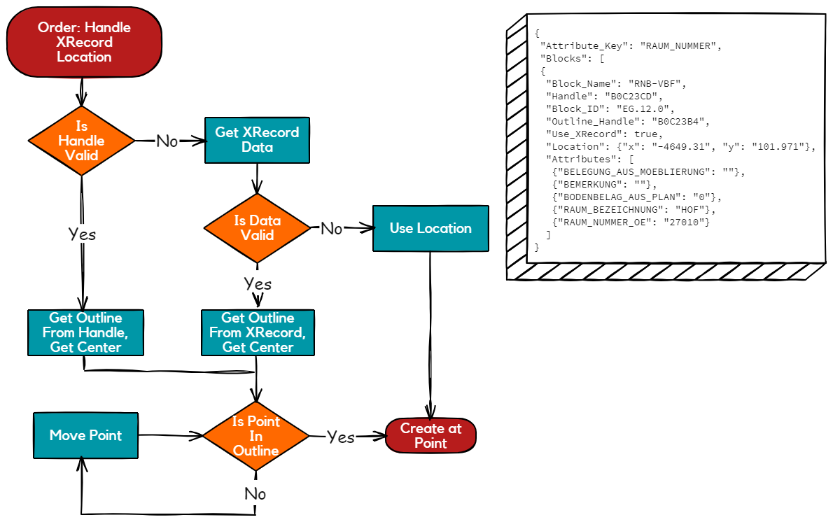
There can be more than one Location form listed for a given block. The order of the Location forms is important in that the Handle and XRecord information must be validated (Handle does not point to a proper polygon or there is no XRecord for that ID). At any point the location is next in the order then the location is used as no validation is required for that.
Processing Order by Handle-Xdata-Location
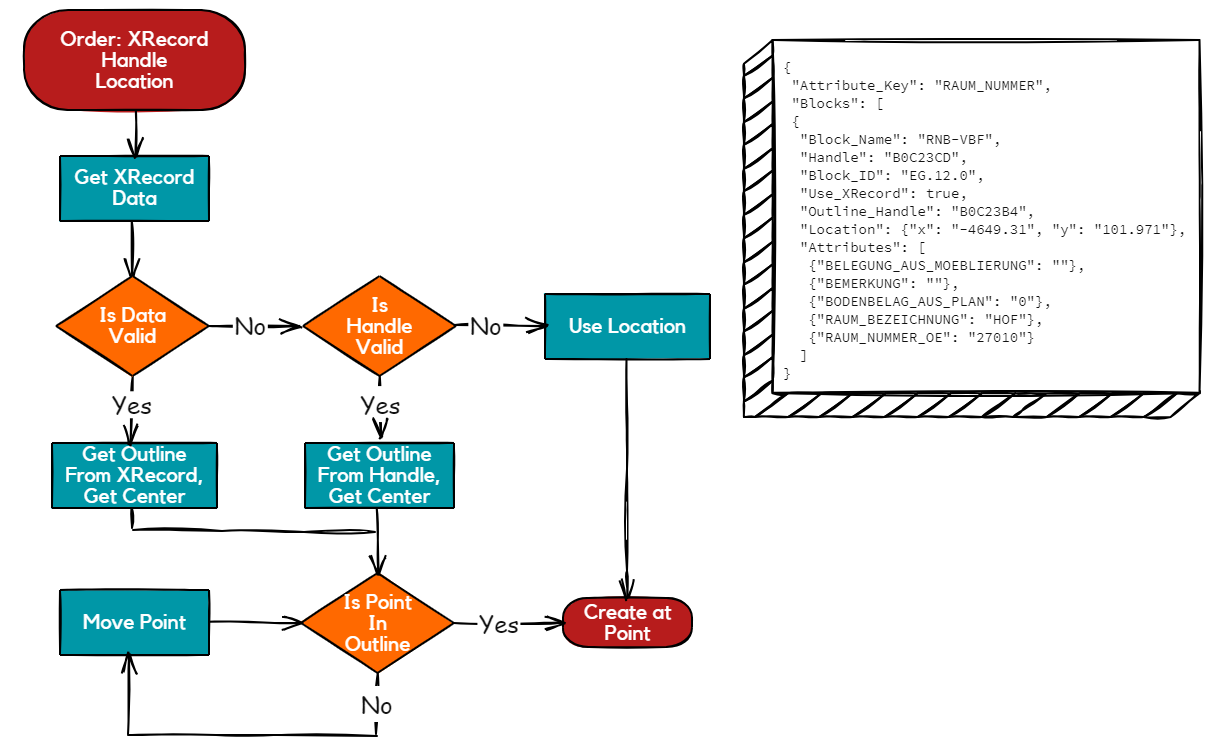
Prcessing Order by Xdata-Handle-Location
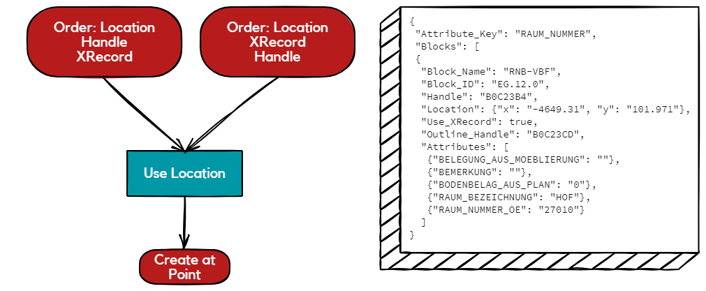
Processing Order by Location
Operation
The Data Update Function is a command line driven operation. The actual command is -du1. The normal parameters are:
- DU1 - The Data Update command listing the JSON command file
- I - Input File, the original DWG file
- O - Output File, the modified DWG file. For safety sake, it cannot be the same as the input file
A sample command line:
-i=<inputfile>.dwg -o=<outputfile>.dwg -du1=<command_file>.json -rl=<roomLayer>
The parameters are:
| Parameter | Purpose |
|---|---|
| -i=<intput_file>.dwg | The input file name, it is usually fully qualified, otherwise it is relative to the current directory |
| -o=<output_file>.dwg | The output file name, it is usually fully qualified, otherwise it is relative to the current directory. It cannot be the same as the inputfile name |
| -du1 | The Data Update command. The parameter value is the name of the JSON file containing the revised block information |
| -rl=<roomLayer> | The Layer of the Room Polygon [the polygon that surrounds each defined room in the drawing]. This is RAU-PL for BoA drawings. RL (RoomLayer) can be either on the command line or in the JSON file |
A minimal JSON file used for DU1 (where RL is defined on the command line) would be:
{
    "Attribute_Key": "RAUM_NUMMER",
	"Blocks" : [
	{
		"Block_Name": "RNB-VBF",
		"Block_ID": "EG.12.0",
		"Attributes": {
			"RAUM_BEZEICHNUNG": "Courtyard",
			"RAUM_NUMMER_OE": 666,
			"BODENBELAG_AUS_PLAN": 0
		}
	}
	]
}
Limitations
There are a number of limitations imposed by this architecture
- There can be only one Space Block defined per Room
- The architecture will work for other types of Blocks, but if more than one block of a given type is in a Room then the Block Handle must be listed or it will be unable to identify which Block is being updated