Data Extraction -Operation
Background
Bank of XXXXXXX uses a combination of AutoCAD DWG drawings and Planon for «space planning». There is a multi-step process that involves synching data between AutoCAD and Planon several times. Much of the data is sourced from Planon and then stored in the AutoCAD drawing.
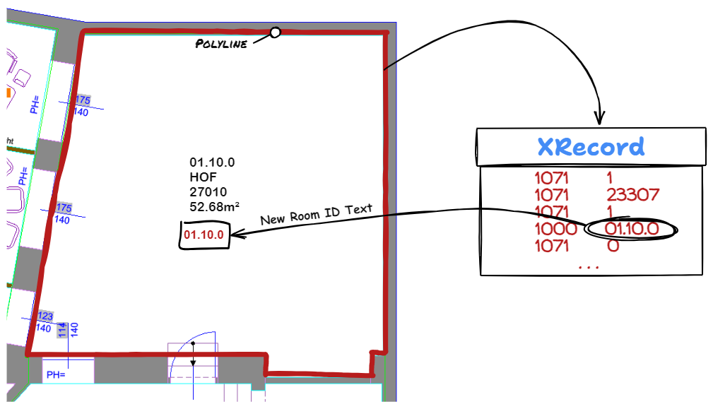
The basic operation involves storing Planon data as Extended Entity Data (known as XData) and Extended Dictionary Records (known as XRecords) attached to Polylines in the AutoCAD drawing. That data is then used to create Space Stamps and Rental Stamps (and other stamps for lockers, etc.) in the AutoCAD file.
Types of Blocks
The Bank of XXXXXXX drawings have the following types of Blocks used in them:
- WLAN-Sender
- RNB-VBF
- SAN-URINAL
- ERSTE-HILFE
- RNB-BSP
- BS-Nordpeil
- IT-DR
- SBM-CHAIR-V
- Messpunkt
- Panos E200 LED 18W LDO
- Raumthermostat
- SBM-ZA
- SE-DREH
- SE-BES-M-ARM
- SBM-NR
- D-AP-CAMPUS
- RNB-MVG
Currently all of these are output to the JSON data files, but Phase Two will have the ability to select which Blocks are output. The Block Data including all Attributes are output to the JSON.
Block Data and Attributes
A typical Block is shown below.
- Name - type of block (see the list above)
- Handle - the unique identifier of the Block Reference (instance)
- ID - the ID (RAUMNUMMER in the case of Band of XXXXXX) that defines what area the Block Reference is in
- Layer - the AutoCAD Layer the Block Reference is on
- Location - the DWG coordinates of the insertion point of the Block Reference
- Attributes - any and all Attributes associated with this Block Reference. This is defined using a Tag (Name)/ Value pair, plus whether the Attribute is visible on the drawing (usually in the form of a stamp, a Space Stamp in this case).
				{
				"Name": "RNB-VBF",
				"Handle": "142E7",
				"ID": "01.10.0",
				"Layer": "BE-T-RNBVBF",
				"Location": {"x" : "-233.209", "y" : "525.266", "z" : "0"},
				"Attributes": [
							{
							"Tag" : "RAUM_NUMMER",
							"Value" : "01.10.0",
							"Visibile" : "true"
							},
							{
							"Tag" : "RAUM_BEZEICHNUNG",
							"Value" : "GARD-D",
							"Visibile" : "true"
							},
							{
							"Tag" : "RAUM_NUMMER_OE",
							"Value" : "27000",
							"Visibile" : "true"
							},
							{
							"Tag" : "BODENBELAG_AUS_PLAN",
							"Value" : "0",
							"Visibile" : "false"
							},
							{
							"Tag" : "FLAECHE",
							"Value" : "10.13 m²",
							"Visibile" : "true"
							},
							{
							"Tag" : "RAUM_NUMMER_PLATZHALTER",
							"Value" : "01.10.0",
							"Visibile" : "false"
							},
							{
							"Tag" : "BEMERKUNG",
							"Value" : "Garderobe Damen",
							"Visibile" : "false"
							},
							{
							"Tag" : "ID_RNB",
							"Value" : "10.13 m²",
							"Visibile" : "false"
							},
							{
							"Tag" : "RAUM_MIETEINHEIT",
							"Value" : "155-T1",
							"Visibile" : "false"
							}
					]
				},
XRecord Data
Each room in the building for Bank of XXXXXX has a polygon on Layer RAU-PL that defines the area for that room (the Room Polygon). The Space Stamps and other stamps are contained within a room and we use the Room Number (Raum-Nummer) as the key ID for the room.
Each Room Polygon can have an associated XRecord containing information about that room.
The XRecord for the Room Polygon enclosing the Space Stamp shown above is shown below. The RaumNummer is contained in the first “1000” code item (01.10.0) and the Bemerkung is the third “1000” code item (Garderobe Damen). The remainder of the items are largely in the XRecord appear to be ordinals corresponding to places in a data table.
1071     1
1071     23307
1071     1
1000     01.10.0
1071     0
1071     0
1071     0
1000     ""
1071     1
1000     Garderobe Damen
1071     0
1071     0
1071     0
1071     0
1071     0
1071     0
1071     0
1071     0
1071     1
1071     61
1071     0
1040     0.0
1071     1
1071     5653
1071     1
1071     49
1071     0
1071     0
1071     1
1071     46
1071     1
1071     43
1071     0
1040     0.0
1071     0
1040     0.0
1071     0
1040     0.0
Operation
There are three parts of the operation:
- Data Extraction to extract Block Information
- Data Update to change, delete or add Blocks
- File Conversion to create the SVG file for use in display
Data Extraction
The Data Extraction step goes through the AutoCAD DWG file to extract the Block Information related to the Stamps. Phase One operation extracts all blocks while Phase Two operation will be able to limit to a subset of the blocks in the file.
Phase One Command Line
ax2024 <inputfile>.dwg -dx1 -rl=RAU-PL
<b
The minimal set of parameters is:
- Input File
- Command (-dx1 in this case)
- Room Layer (The layer where the room polygons are drawn, RAU-PL in this case)
Other parameters are:
- License File Location (-lpath=
) - this defaults to the location of the input file and then the location of the executable.
Phase Two Command Line
ax2024 <inputfile>.dwg -dx1=<parameters>.json
The minimal set of command line parameters is:
- Input File
- Command (-dx1 in this case, with optional JSON parameter file listed)
Parameters that can be defined on either the command line or in a JSON parameter file:
- Block Name Layer - Layer(s) where blocks (stamps) are defined
- Block Name - Names of blocks (stamp) to be processed
- Room Layer - The layer where the room polygons are drawn
- License File Location (-lpath=
) - this defaults to the location of the input file and then the location of the executable.
Data Update
Phase One
In Phase One the Data Update takes the Room Id (RAUM_NUMMER) from the XRecord attached to the Room Polygon and creates a text entity on a hidden layer whose contents are the Room Id.
ax2024 <inputfile>.dwg -du1 -rl=RAU-PL
Phase Two
The main Data Update step is a Phase Two function. It will allow reading in a JSON file with the same format as produced in the Data Extraction step and allow:
- Changing Blocks
- Deleting Blocks
- Adding Blocks
The command line will be described in detail with Phase Two. The command is -du1.