CADViewer, with it’s flexible design and use of standard toolkits, can be integrated with any Data Management Application and be used with a multitude of custom data-driven applications. See our AI Presentation Video for an outline of the business case around the CADViewer AI Technology.
Computing Distances and Adjacency
Knowing how far apart two things are can be very important. We will examine distances as they relate to a shopping mall, but other types of locations are equally valid. This is all based on our Geometrical Algorithm.
The CADViewer back-end converter AutoXChange used to create the spatial relationships that are used with LLM queries and RAG information retrieval, has two distinct distance calculations: straight-line and walking.
This article examines computing distances and adjacency between spaces in drawing. CADViewer AutoXChange has two distinct distance calculations: straight-line and walking.
We will examine the background of the process, the setup requirements for drawings using the “Walking Distance” method, and the command line and JSON file requirements for running both calculation methods.
Background
Knowing how far apart two things are can be very important. We will look at two methods of computing distances: straight-line and “walking”.
We will examine distances in relation to a shopping mall, but other types of locations are equally valid.
Computing Distances
Straight-line
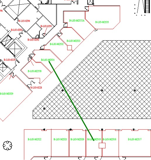
Straight-line distance, sometimes known as “as the crow flies”, is the distance from one point to another, regardless of what is in the way. While that may be ideal for traveling from one town to another, within a building or complex of buildings, the straight-line distance is not entirely accurate. Most people, when going from Store A to Store B, do not want to go through walls, cut across streets in the middle of the block, or jump from balcony to balcony. So, while straight-line distance is better than nothing, it does not provide an accurate portrayal of the distance between two points in such a scenario.
Walking Distance
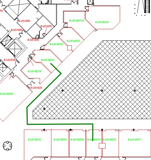
Walking distance is the distance it would take to walk in a usual manner from one point to another. It may navigate around corners, cross intersections, and utilize doors to exit rooms. In other words, it will measure the distance a typical person would need to travel from Point A to Point B. Usually, there will be multiple paths that could be followed, and AutoXChange will compute the shortest distance from those alternatives.
Straight-Line Distance
Walking Distance
Drawing Requirements
Straight-line distance has minimal requirements for drawings. Essentially, a point is needed in each space to act as the endpoint of a line connecting one space to another. Typically, this is the anchor point of the name or ID of the space, but it can be a separately defined point if desired. A point that marks the door of the space would be ideal.
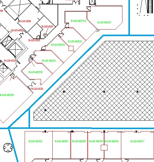
Walking distance has one required and one optional layer. The CorridorLines layer defines the paths that are allowed for traversal between spaces. Paths must be specified using Line or Polyline (both LW Polylines and 2D Polylines, but not 3D Polylines) elements. Polyline Bulge segments (arcs) are ignored. Only junctions between paths that meet at a single point are considered. Junctions are allowed at any Polyline Vertex, not just at endpoints. However, Polylines or Lines that cross, but do not meet at a common point, are not considered junctions and will be treated as separate paths.
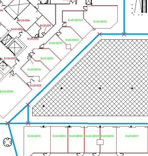
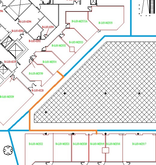
These paths are defined by the Blue lines in Figure 3 below. The junctions between paths are shown in Figure 4 as Red Crosses.
Corridor Lines
Junctions Lines
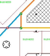
Examining Junctions in more depth, Figure 5 shows four Corridor Lines: an orange polyline with a bend at the middle vertex and three lines (or polylines) - blue, purple, and yellow. There are only two Junctions - between the blue line and the middle vertex of the orange polyline, and a three-way junction between the purple and yellow lines and the end of the orange polyline. There is no junction where the purple and blue lines cross. There must be an endpoint or a polyline vertex for a junction, and crossing lines do not count.
Junctions
To calculate the Walking Route, the shortest distance from the spaces at each end to the nearest Corridor Lines is computed. The routes between the two points on the Corridors are added to the distance from the end rooms, and the resulting sum is the distance. This results in the Orange lines in Figure 6 below.
Walking Route
Command Lines
See the general documentation on AutoXchange command interface.
The command for computing distances using the Straight-Line Distance calculation is -ODD, for Output Direct Distance.
-i=<inputfile>.dwg -o=<output file>.json -odd [-json=<parameter_file>.json]
| Command | Name |
|---|---|
| ODD | Output Direct Distances |
| RLayer (RL) | Defines Layer for Room Outlines (closed polylines that define each space) |
| TLayer (TL) | Defines Layer for Room IDs (Room IDS must be Text or MText elements) |
Note: The RLayer and TLayer commands can be inside an optional JSON file that is defined using the -json parameter (-json=<parameter_file>.json).
{
  "Parameters": {
    "rl": [
      "SF-TENANT-PL"
    ],
    "tl": [
      "BI-TEXT"
    ]
  }
}
The command for computing using the Walking Distance calculation is -ODJ or -OutputDistances. However, if the minimal drawing requirements are not met, then Straight-Line Distance will be used instead. Of course, an error message will be output explaining why Direct Distances were used instead of Walking Distances. The presence of the Corridor Lines layer (as defined by the -CorridorLines parameter) with at least one Corridor Line defined on it is required.
-i=<inputfile>.dwg -o=<output file>.json -odj [-json=<parameter_file>.json] -CorridorLines=Corridor [-BlockingLines=Blocking]
| Command | Name |
|---|---|
| ODJ | Output Distances to JSON |
| RLayer (RL) | Defines Layer for Room Outlines (closed polylines that define each space) |
| TLayer (TL) | Defines Layer for Room IDs (Room IDS must be Text or MText elements) |
| CorridorLines (CX) | Defines the Corridor Lines Layer |
| BlockingLines (BX) | Defines the Blocking Lines Layer |
Note: The Room Layer, Text Layer, CorridorLines, and BlockingLines can be defined in a JSON Parameter file as part of the Parameters Section.
{
  "Parameters": {
    "rl": [
      "SF-TENANT-PL"
    ],
    "tl": [
      "BI-TEXT"
    ],
    "cx": [
      "CorridorLines"
    ],
    "bx": [
      "ARCH-WALLS-INTERIOR",
      "ARCH-WALLS-EXTERIOR"
    ]
  }
}
Blocking Lines are lines or polylines that walking routes cannot cross. These represent solid walls or areas that are out of bounds to customers, for instance, supply corridors. This is used to generate the line segment from the anchor point in the space to the nearest Corridor Line. Connections along Corridor Lines between Junctions are presumed to be using a door through any Block Lines.
Adjacency
Adjacency measures whether two areas (rooms, stores, etc.) are “right next” to one another. In practice, one building could be drawn with thickness to inner walls, while a second drawing might represent such walls with no thickness. Even in the same drawing spaces that are next to one another, there might actually be a minimal distance between them. This is why AutoXChange allows a tolerance to be defined and treats any spaces that are separated by that tolerance or less as “Adjacent”.
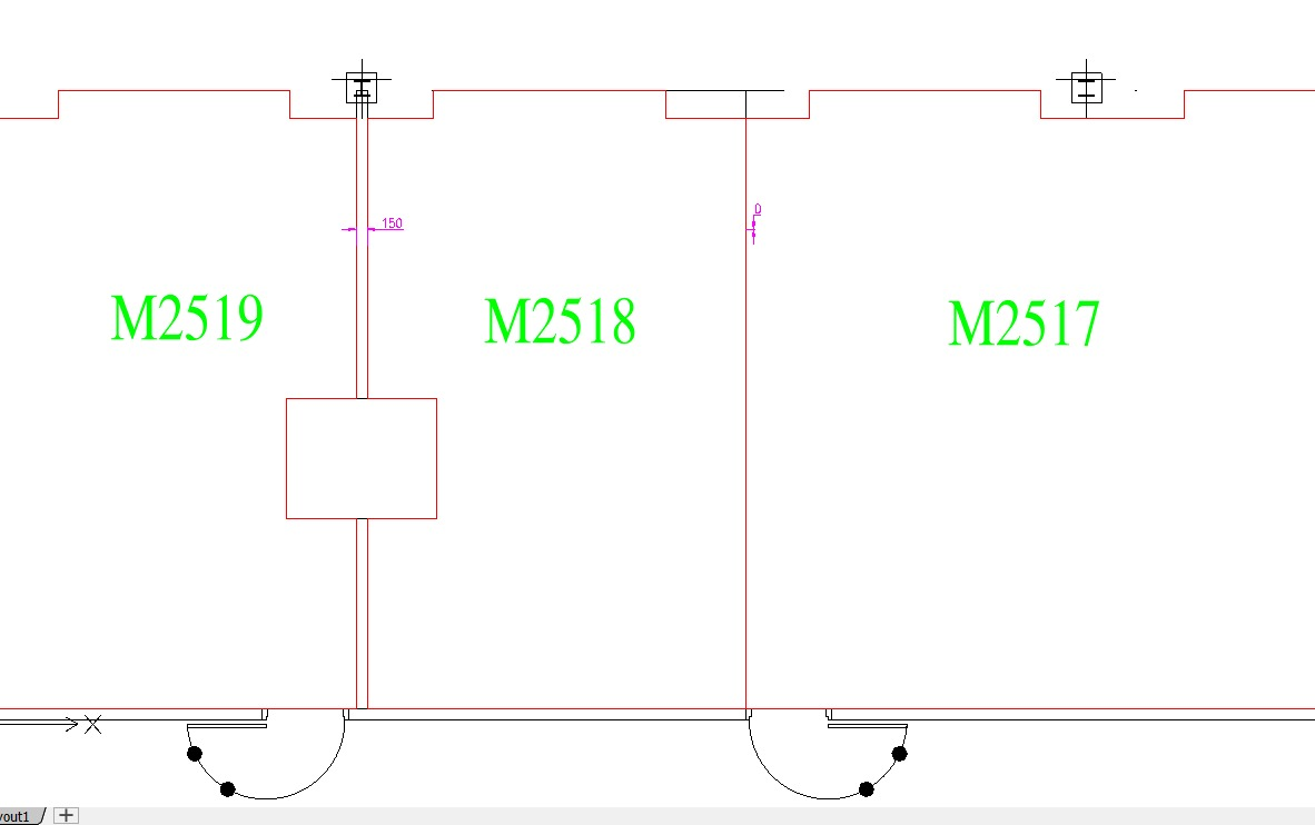
In the above image, you can see that M2519 is separated from M2518 by 150 mm, but M2518 and M2517 are 0 mm apart. If the tolerance is 100mm, then M2518 is adjacent to M2517, but not to M2519. If the tolerance is 200 mm, then it would be considered adjacent to both spaces.
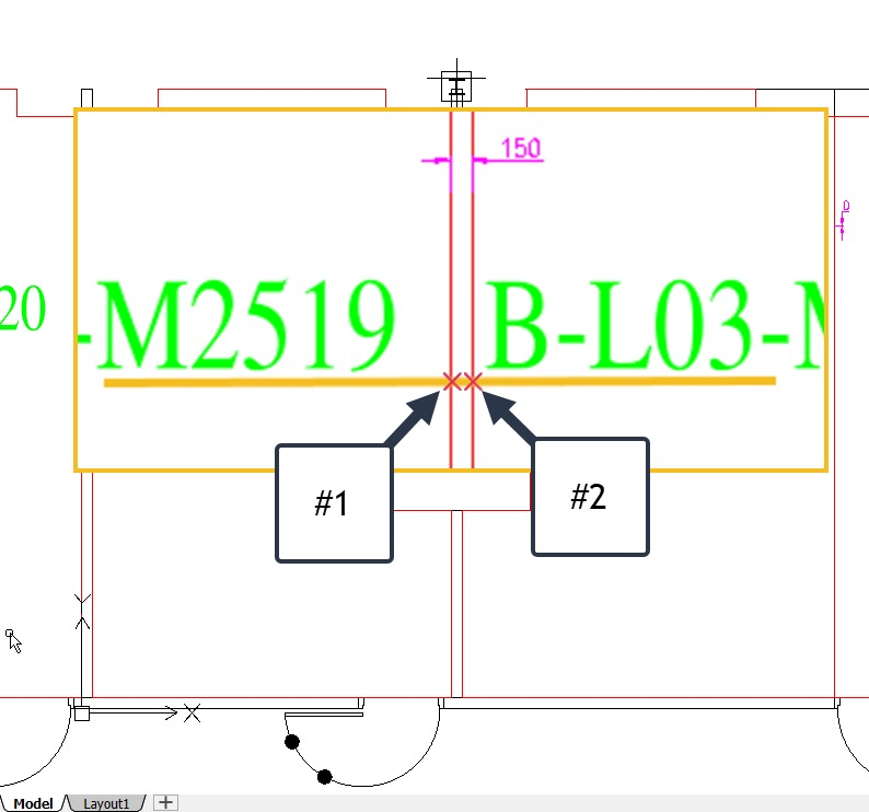
How is this calculated? Essentially, we draw a line from a point within Space #1 to a point within Space #2. We typically use the anchor point of the Room IDs as the endpoints of the line, but this can be changed. The points where that line crosses the Room Boundary of each space are calculated, and if the distance between those points of intersection is less than the tolerance described above, then the spaces are adjacent.
Command Line
There is no separate command to include adjacency calculations. If either Straight-Line or Walking Distances is computed, then adjacency is also computed. This does mean that adjacency cannot be computed without also doing a distance calculation.
For More Details
Please contact us on: Contact Information
Please Register and test the online CADViewer Demo with CADViewer AI.