CADViewer, with it’s flexible design and use of standard toolkits, can be integrated with any Database Management Application and be used with a multitude of custom data-driven applications.
This Tutorial
This tutorial will outline various ways of creating Interactive Hotspots in drawings using the Tailor Made Software tools suite:
- 1: Automated Creation of Hotspots.
- 2: Create Automated Hotspots using AutoXchange 2024.
- 3: Create Automated Hotspots using CADViewer.
- 4: Create Automated Hotspots from Blocks.
The steps outlined below can be tested online using our Online Test Sample developed specifically for this guide.
Automated Creation of Hotspots
High level interaction with content is one of the cornerstones of CADViewer and AutoXchange 2024 conversion software.
To generate automated hotspots in CAD drawings, such as AutoCAD DWG or MicroStation DGN drawings, the drawing must contain two layers with specific content that through an automated process are matched to generate a set of interactive objects. The layers that the CAD drawing, in addition to regular graphical content, must contain are:
- 1: A layer with text object IDs. – The Text Layer.
- 2: A layer with polygons that surrounds the text object IDs. – The Room Layer.
An automated process in AutoXchange 2024 will then link the Text and Room layers into interactive objects. The process can be done directly using the AutoXchange command line interface, or it can be done interactively using CADViewer.
Create Automated Hotspots using AutoXchange 2024
Creating hotspots server side with AutoXchange ahead of time instead of doing an on-the-fly conversion from CADViewer can save valuable time and computing resources, especially with very large files.
For small and medium sizes drawings the execution time does not differ much using on-the-fly conversion compared to conversion ahead of time.
The process to create an SVG file with hotspots ahead of time, can be done on both Windows and Linux.
It is illustrated with Windows below, but the process is similar on Linux.
Please Download CADViewer and AutoXchange 2024 and follow general install instructions.
1: Download the reference dwg file hq17_rltl_blocks.dwg.
2: Navigate to the install folder of AutoXchange 2024 (here using Apache PHP CADViewer install folder structure):
C:\xampp\htdocs\cadviewer\converters\ax2024\windows>
3: In AutoXchange 2024 folder, check that the AutoXchange 2024 is running properly:
C:\xampp\htdocs\cadviewer\converters\ax2024\windows>ax2024_W64_xx_yy_zz -?
4: Build the command line, where the following AutoXchange 2024 commands that needs to be used are:
- -i= : input file name, this can also include path
- -o= : output file name, this can also include path
- -f=svg : output format, this must be specified to SVG
- -model : specify the converter to use the model space of the drawing
- -rl= : specify the name(s) of the room layer(s)
- -tl= : specify the name(s) of the text layer(s)
The reference drawing hq17_rltl_blocks.dwg has three different layers with space polygons RM_, RM2_, RM3_ and one layer with space ID text RM_TXT that covers all three layers with space polygons. Therefore, since there are multiple space layers the -rl command can contain multipe layers.
5: Execute the command line.
\xampp\htdocs\cadviewer\converters\ax2024\windows>ax2024_W64_xx_yy_zz -i="hq17_rltl_blocks.dwg" -o="hq17_rltl_blocks.svg" -f=svg -model -tl="RM_TXT" -rl="RM_;RM2_;RM3_"
6: An SVG file with hotspots is now generated:
Move the converted SVG drawing to a folder of choice and associate it with CADViewer, or implement the steps above as part of a batch process.
If there are issues with the conversion step above, you can add the command –trace to the command line. This will give a full trace on how AutoXchange loads files, parameters, etc., and therefore can be used as debug information in setting paths up correctly.
7: As part of the conversion a csv file <filename>..rl is created listing which spaces are linked and which spaces are unlinked. This file can be used to import into a back-end space management system to API control the interaction with the created hotspots.
Create Automated Hotspots using CADViewer
Controlling the creation of Hotspots through AutoXchange 2024 can be done the CADViewer interface. It gives the admin user a graphical understanding of the layer structure and can be used if the layer organization of the file is not known beforehand.
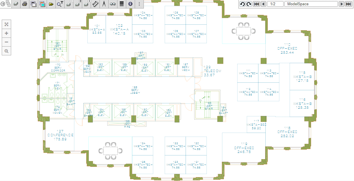
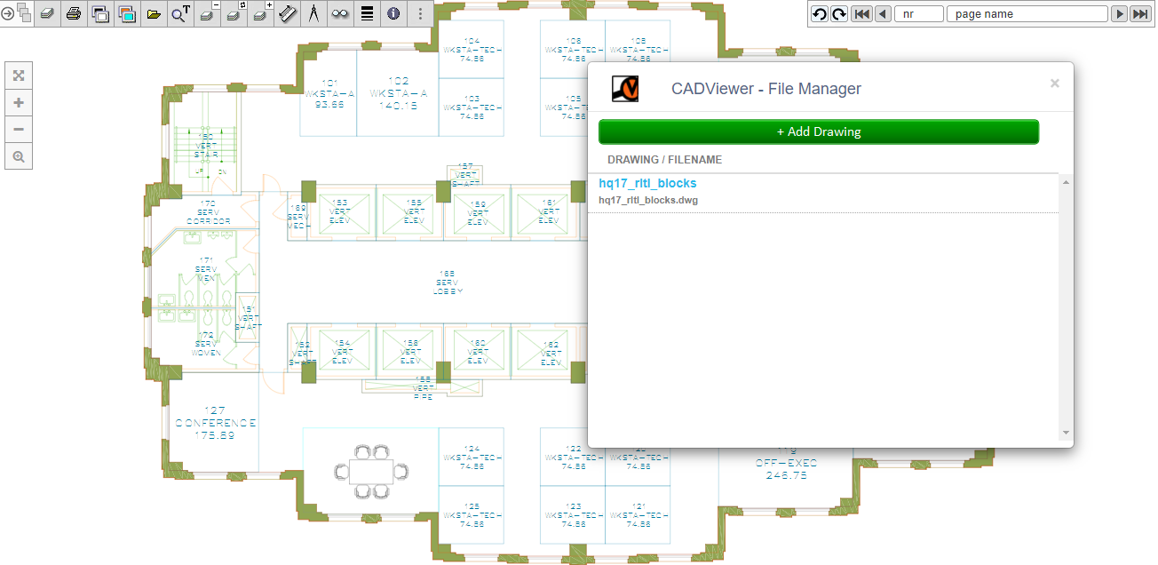
1: Open the Online Sample Drawing in CADViewer.
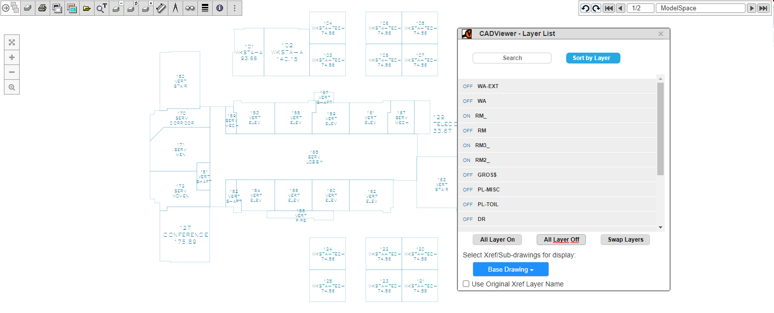
2: In the Online Sample Drawing, use the Layer tool  to find Room Layer(s) and Text Layer(s). Set all layers off, turn on layer RM_, RM2_, RM3_ and RM_TXT. Verify that Space ID’s are inside space polygons.
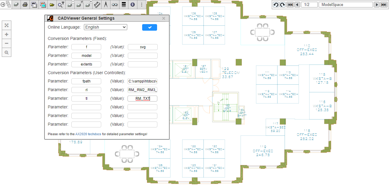
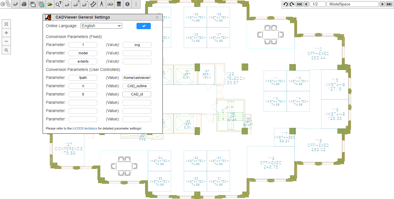
3: In the Online Sample Drawing, use the Settings menu  to add the conversion parameter to the conversion process, to process the layers interactively on next load.
In the Conversion Parameters (User Controlled) section add:
- Parameter: rl (Value): RM_;RM2_;RM3_
- Parameter: tl (Value): RM_TXT
4: In the Online Sample Drawing, reload the drawing  to create hotspots based on parameter settings. AutoXchange 2024 does the automated processing of space objects using the reference layer names.
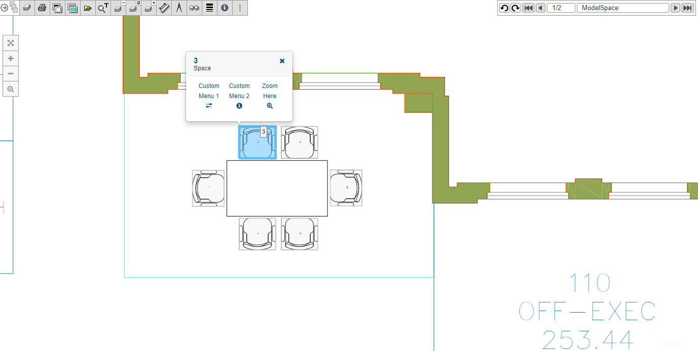
5: Loading of Drawing with interactive hotspots.
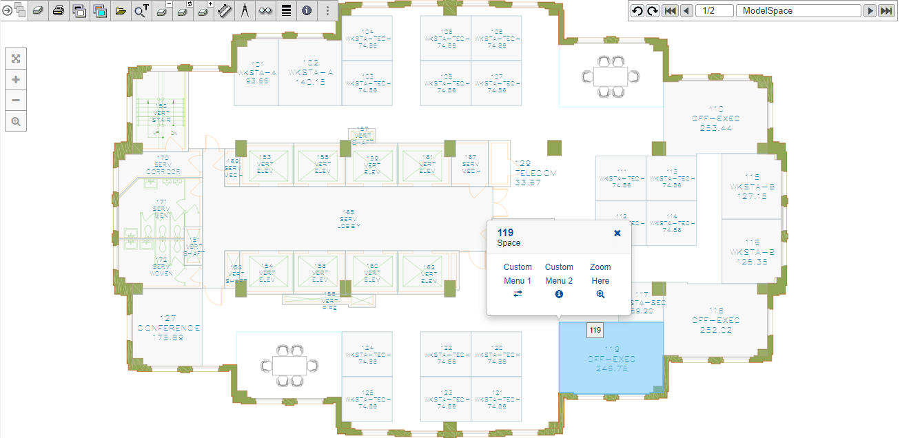
The Drawing now has interactive hotspots. The interactive hotspots can be manipulated on a layer basis, highighted from the API.
See the Sample Documentation for Highlight and Layer Management for more information on using the CADViewer API to control the space objects.
Furthermore the call-out modal is fully configurable and can be set up to interact with database content, please see the resources Custom Modals for Highlight/CAFM and Call-Back Dynamic Modals for Highlight.
Create Automated Hotspots from Blocks
Typically when an asset is placed out on a CAD drawing, it will be repetitive placed out in the drawing. An asset will also typically be represented by a graphical object. In a given drawing, these graphical objects tend to be grouped together in a CAD entity called Blocks.
Tailor Made Software has a technology component DwgMerge 2024 that automated can process blocks in an AutoCAD DWG drawing, and create a new DWG drawing, where the asset blocks are on a form so CADViewer and AutoXchange 2024 can process these to create Interactive Hotspots.
To create automated hotspots from blocks, do the following:
1: First Download DwgMerge 2024 and follow general install instructions.
2: Then download reference drawing hq17_rltl_blocks.dwg
3: Open the drawing in a CAD Editor and identify the assets block names in the drawing. (Here the AutoCAD clone DraftSight is used)
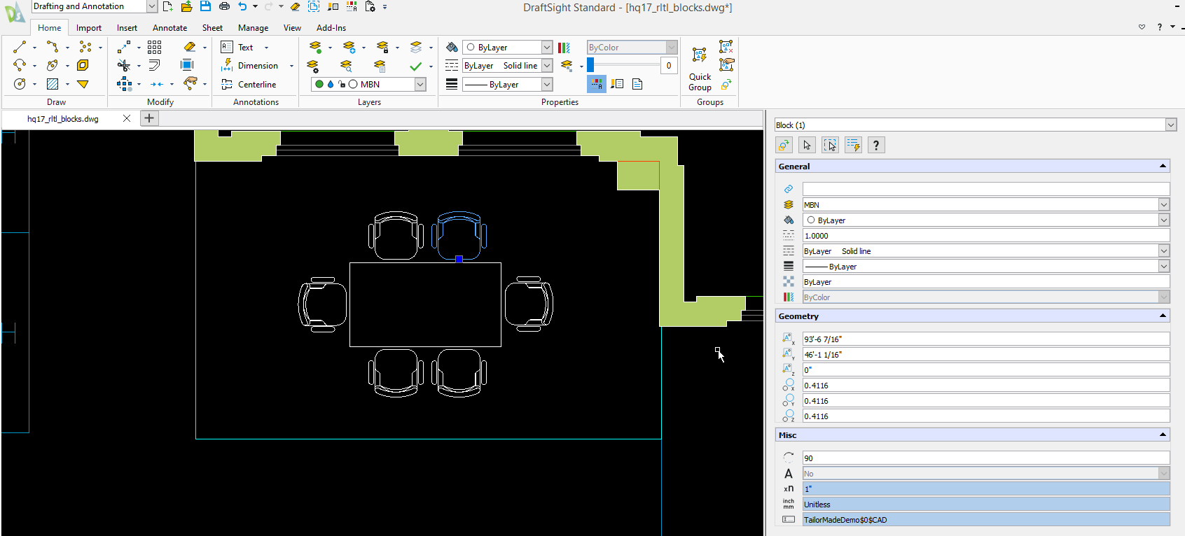
The block name is: TailorMadeDemo$0$CAD
4: Navigate to the install folder of DwgMerge 2024 (here on Windows):
C:\xampp\htdocs\cadviewer\converters\dwgmerge2022\windows>
5: Build the command line, where the following DwgMerge 2022 parameter commands that needs to be used are:
- -base= : base drawing file name, this can also include path
- -out= : output file name, this can also include path
- -over : instruction to overlay content to the file defined by out
- -block_outline= : specify the converter to make an outline of each block
- -block_count= : specify the converter to increment a counter and it write out on each block
- -hyper= : instruction to execute block_outline and block_count
The reference documentation for DwgMerge 2022 can be found here.
6: Execute the command line.
C:\xampp\htdocs\cadviewer\converters\dwgmerge2022\windows>DwgMerge_W32_20_xx_yy -base="hq17_rltl_blocks.dwg" -block_count="TailorMadeDemo$0$CAD" -block_outline="TailorMadeDemo$0$CAD" -out="hq17_rltl_blocks_processed.dwg" -over -hyper
7: DwgMerge 2022 will process the blocks, and create a new DWG drawing.
Count Blocks: TailorMadeDemo$0$CAD
Outline Blocks: TailorMadeDemo$0$CAD
             DwgMerge 2022  V20.01.07b
     Copyright (c) 2019 Tailor Made Software, Ltd.
                 All Rights Reserved

============================================================

Base File: hq17_rltl_blocks.dwg
Count Blocks: 1
Block NameTailorMadeDemo$0$CAD
Create block layerCAD_id
Create Text Object: 1
Create Text Object: 2
Create Text Object: 3
Create Text Object: 4
Create Text Object: 5
Create Text Object: 6
Create Text Object: 7
Create Text Object: 8
Create Text Object: 9
Create Text Object: 10
Create Text Object: 11
Create Text Object: 12
OutlineBlocks: 1
Name: TailorMadeDemo$0$CAD
Writing To File: hq17_rltl_blocks_processed.dwg
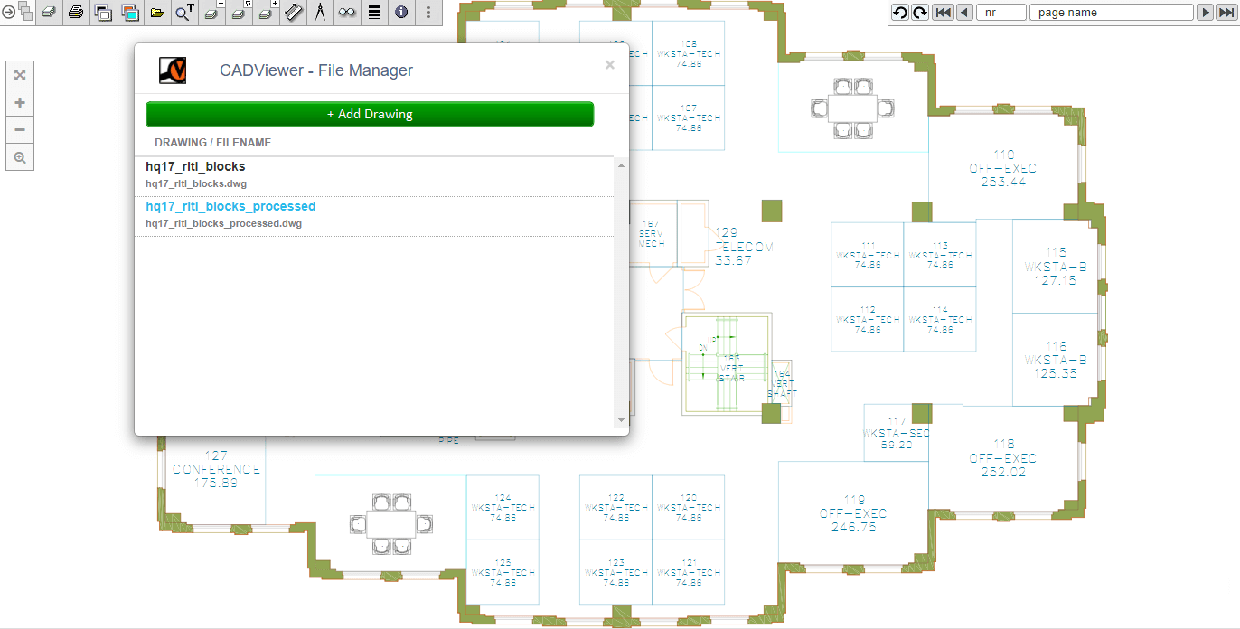
8: You can download the converted drawing hq17_rltl_blocks_processed.dwg
9: The layers created by DwgMerge 2022 are named after the blockname after the rightmost $ delimiter in the blockname TailorMadeDemo$0$CAD, therefore the text layer is CAD_id and the space layer is CAD_outline.
10: To create Automated Hotspots using AutoXchange 2024 simply redo the process described above, but change the rl/tl parameters.
\xampp\htdocs\cadviewer\converters\ax2024\windows>ax2024_W64_xx_yy_zz -i="hq17_rltl_blocks_processed.dwg" -o="hq17_rltl_blocks_processed.svg" -f=svg -model -tl="CAD_id" -rl="CAD_outline"
11: To verify the process online, go to the Online Sample Drawing.
12: In the Online Sample Drawing, use the Settings menu to add the conversion parameter to the conversion process, to process the layers interactively on next load.
In the Conversion Parameters (User Controlled) section add:
- Parameter: rl (Value): CAD_outline
- Parameter: tl (Value): CAD_id
13: In the Online Sample Drawing, load the drawing to process hq17_rltl_blocks_processed.dwg to create hotspots based on parameter settings. AutoXchange 2024 does the automated processing of space objects using the reference layer names.
14: The Asset Chairs now higlights and can be accessed throught the CADViewer API.